UML
Flowcharts for dummies
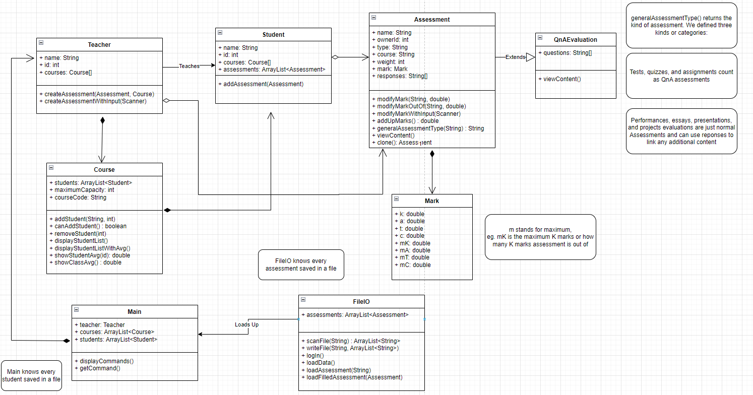
A UML diagram, or a Unified Modeling Language diagram, is a way for programmers to represent software as a visual. This is done through a series of arrows and boxes creating a sort of flowchart pattern. However, UML diagrams wont fully display everything going on in a program. Methods aren't written out as a UML is only supposed to describe classes and its interactions with other classes. UML diagrams should not be the only thing done in the planning process. UML diagrams can be made either using pencil and paper, or using software such as draw.io.
How to Make a Class
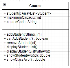
To make a class in UML, you first need a box with 3 sections. On the top most box, the name of the class should be written down. The middle box should contain the fields of the class, following a "+fieldName: ObjectType" format. The the last box, methods should be put. Mutators and accessors do not need to be inserted here as they are assumed to exist. The methods should be written in the following format: "+methodName(paramsTypes): returnType" If you have a void method, it is not required to have the return type section filled out. See the example on the right.